Ebay low pass filter for HF.

Some time ago i bought a HF LP filter from Ebay.  As normal it did come with minimal documentation.Capture

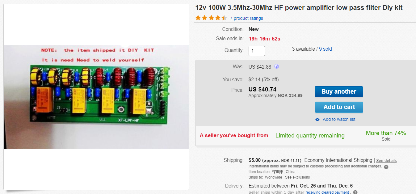
After some e-mails back and forth i managed to get the required documentation form the seller.

Here are the component values.

C1 C3 C5:820P
C2:1500P
C4 C6:430P
C7 C9 C11:180P
C8:330P
C10 C12:100P
L1 L2:22T (Red toroide Amidon T50-2 ?)
L3 L4:16T (Red toroide Amidon T50-2 ?)
L5 L6:11T (Yellow toroide Amidon T50-6 ?) (L7 & L8 on the PCB)
L7 L8: 8T (Yellow toroide Amidon T50-6 ?) (L9 & L10 on the PCB)

The PCB is not 100% according to the buildings instruction, but as the capacitors are in sequential order the inductors are also follow a sequence just add 2 in the inductor name after L4.

I suspect that running 100W on these toroides might be a bit than what they are capable of.

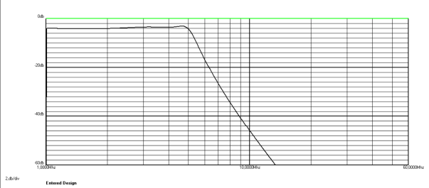
I have done a simulation in AADE filter software for all filters.  The AADE web site is no longer active but the software can be found on other sites.
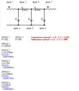
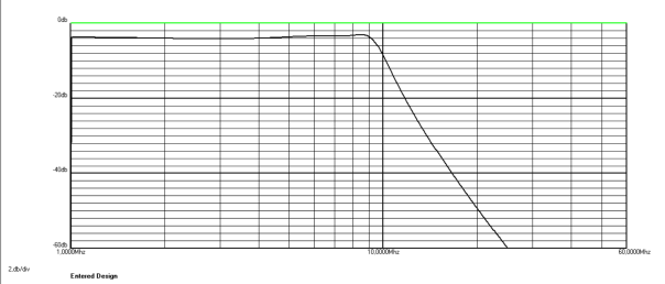

80 m filter.

The filter has a roll off at about 4,5 Mhz. making it capable for 80m but not 60m.
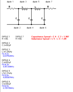
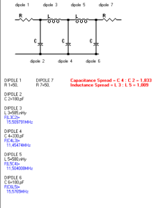
5M Filter Schem

5M Filter plot


60 m & 40 m filter.

This filter has a roll off close to 9 Mhz. and is capable of 60m and 40m.

8M Filter Schem

8M Filter plot


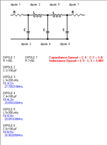
30 m, 20 m & 17 m filter.

This filter has a roll off close to 19,9 Mhz. and is capable of 30 m to 17 m.

20M Filter Schem

20M Filter plot


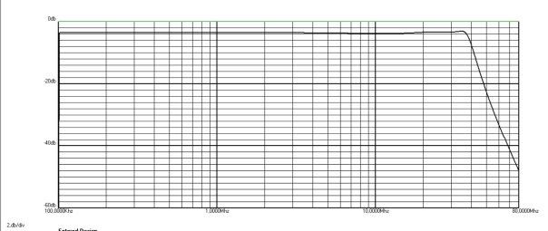
15 m, 12 m & 10 m filter.

This filter has a roll off close to 35,5 Mhz. and is capable of 15 m to 10 m.
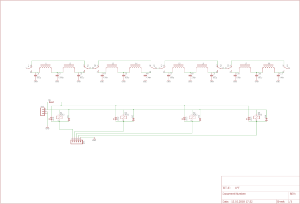
30M Filter Schem

30M Filter plot


Schematics.

The schematics where made by tracing the PCB. I can not guarantee

Filter

Parts list


Harmonics.

When the filter is assembled i will do a sweep with the spectrum analyzer to determine the actual filter curve.

As long as I’m got 43 dB suppression on the fundamentals it will comply with the ITU recommendations found in ITU-R SM.329-10.

Some fine tuning might be required to obtain this attenuation.


This will be a on of project going through the winter and in the end be a part of a complete linear with approximately 50 W SSB at 12V.

Filter.

Because of all the harmonic some filtering is required.

I decided to use a combination of high-pass and low-pass filter.   The most important about the filters is to get the harmonics down with at least -60dB or better than the local oscillator frequency. The reason for this LP/HP combination is that the filters is simpler to trim and the band-pass is simpler to adjust, the drawback is some higher losses.But since I will use a buffer amp after the filters a loss of a few dB is not the big concern. The filters where designed with AADE filter software.


Schematics and plot for high pass filter.

HP filter 40MHz sch

HP filter 40MHz

EHP 40mhz

Schematics and plot for low pass filter.

LP filter 43MHz sch

43MHz LP filter plot

ELP 43mhz a

The EHP 40mhz must be renamed from .key to .sch to be able to open it in AADE filter software.

Trace.

Trace of filter smoothed with 100 samples.

f

Trace of filter and oscillator smoothed with 100 samples.

osc fil


As you can see there is a bit of loss in the filters, but I’ll make a tuned input buffer amp to get rid of the harmonics on 14 MHz, 56 MHz and 84 MHz.

Oscillator multiplier.

Oscillator

Here is the schematics of the oscillator multiplier. It multiplies from 14MHz to 42 MHz.

The design of the multiplier gives a lot of harmonics all the way up to the 21 order at 294 MHz. This might be a good oscillator for transverters all the way up to the 23cm band with a 2GHz transistor. The output transformer will have to be an air-core transformer.

Quick about the circuit.

R1: 47Ω

R2: 10kΩ

R3: 4k7Ω

R4: 300Ω

C1: 0,1μF

C2: 45,5 pF @ 14MHz or 30,32 pF @ 21MHz. I used a 50 pF trimmer.

C3: Ca 40pF @ 14MHz or 50pF @ 21MHz.

T1:  250Ω 14 MHz; 2,83μH, 19T 10mm core 12 mm long. 0,202mm enameled cu wire. Secondary is 10-20% of primary.

T1: 250Ω 21 MHz; 1,89μH, 14T 10mm core 9 mm long. 0,202mm enameled cu wire. Secondary is 10-20% of primary.

To calculate the I used two web pages. The Daycounter for calculating the required inductance and www.circuits.dk to calculate number of turns on the inductor.

66pacific.com does also have a good calculator to reverse engineer the inductors in the schematics.

As showed in the picture there are harmonics up to 21 order, the harmonics over 14 order are more or less neglectable.

osc