I’m no expert on programming and have found this method to get the USB working on the Bluepill. There might be a better way to get this to work, but this works for me!
R10 modification.
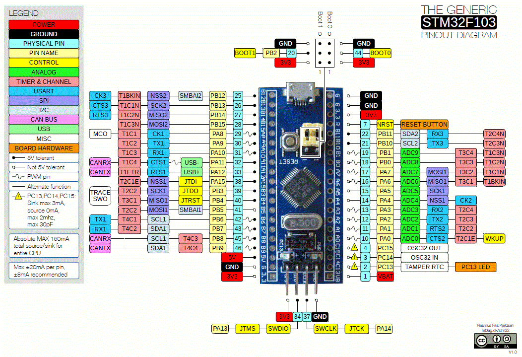
First ting i did was to do the R10 modification on the Blue pill. This is the pullup resistor for the USB+ line. There are boards with 10k (marking 103) and 4k7 (marking 472) but the correct value is 1k5 (marking 152), but I’m not certain that it is critical because i use a 10k & 2k2 in parallel (1k8) and this works.
The resistor is in size 603 and can be hand soldered with good light and a fine tip on the soldering iron.
Another option is to just leave the resistor in place and connect a 1k8 regular resistor from 3,3V supply to pin PA12. 3,3V can be found in 5 diffrent places on the board the simplest is probably on the J-tag header to PA12 or to the end of R10 closes to the pin-header.

I did not have the correct resistors available and ended up doing a bit of creative modification to get the mod done.
Finding the correct boot-loader.
There are several boot-loaders that can be found on the internet. As far as I know all are based on the Maple-leaf development board. Over the years there have ben done modifications on the boot-loader and Roger Clark har been a major player in this development. Thank you Roger!!!
https://github.com/rogerclarkmelbourne/STM32duino-bootloader
For the Blue pill I have used the boot-loader called «generic_boot20_pc13.bin» that can be found in the binaries folder.
Flashing the boot-loader.
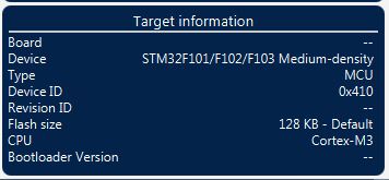
I have used the STM32Cube programmer to upload the Boot-loader to the chip.
https://www.st.com/en/development-tools/stm32cubeprog.html
You need to put in some personal information like e-mail and name to get access.
The usage of the programmer is pretty simple.
- Connect to the MCU by selecting the correct interface. In my case i used a USB to serial converter with a FTDI chip. RX : PA9, TX : PA10, GND : GND, 3,3V : 3,3V. Remember to set the serial converter to 3,3V otherwise you will damage the MCU
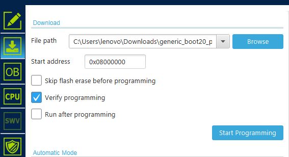
- Go to the download tab.
- Select the correct boot-loader form Rogers Git. «generic_boot20_pc13.bin«
- Configure the upload according to the picture and click «start programming»

Adding board definitions to Arduino IDE.
Now its time to set up the Arduino IDE!
First add the line. «https://github.com/stm32duino/BoardManagerFiles/raw/main/package_stmicroelectronics_index.json» to the preference in the Arduino.

Then go into the board manager and select the STMicroelectonics board definitions. Just put STM in the search field and select the ones form STM. If you have some other STM stuff installed just uninstall it if you dont need it.

Setting up Arduino IDE for uploading a sketch.
I had to play a bit with the configuration of the Arduino to get it to work. The configuration in the picture shows my working configuration. The upload of the sketch where done with the same wiring as when the boot-loader where flashed.

