STM32 Bluepill with USB working.

I’m no expert on programming and have found this method to get the USB working on the Bluepill. There might be a better way to get this to work, but this works for me!

This picture can be found several places on the internet.

R10 modification.

First ting i did was to do the R10 modification on the Blue pill. This is the pullup resistor for the USB+ line. There are boards with 10k (marking 103) and 4k7 (marking 472) but the correct value is 1k5 (marking 152), but I’m not certain that it is critical because i use a 10k & 2k2 in parallel (1k8) and this works.

The resistor is in size 603 and can be hand soldered with good light and a fine tip on the soldering iron.

Another option is to just leave the resistor in place and connect a 1k8 regular resistor from 3,3V supply to pin PA12. 3,3V can be found in 5 diffrent places on the board the simplest is probably on the J-tag header to PA12 or to the end of R10 closes to the pin-header.

I did not have the correct resistors available and ended up doing a bit of creative modification to get the mod done.

Finding the correct boot-loader.

There are several boot-loaders that can be found on the internet. As far as I know all are based on the Maple-leaf development board. Over the years there have ben done modifications on the boot-loader and Roger Clark har been a major player in this development. Thank you Roger!!!

https://github.com/rogerclarkmelbourne/STM32duino-bootloader

For the Blue pill I have used the boot-loader called «generic_boot20_pc13.bin» that can be found in the binaries folder.

Flashing the boot-loader.

I have used the STM32Cube programmer to upload the Boot-loader to the chip.

https://www.st.com/en/development-tools/stm32cubeprog.html

You need to put in some personal information like e-mail and name to get access.

The usage of the programmer is pretty simple.

  1. Connect to the MCU by selecting the correct interface. In my case i used a USB to serial converter with a FTDI chip. RX : PA9, TX : PA10, GND : GND, 3,3V : 3,3V. Remember to set the serial converter to 3,3V otherwise you will damage the MCU
  2. Go to the download tab.
  3. Select the correct boot-loader form Rogers Git. «generic_boot20_pc13.bin«
  4. Configure the upload according to the picture and click «start programming»
MCU info from STM32 Cube

STM32F103C8 with boot-loader

Adding board definitions to Arduino IDE.

Now its time to set up the Arduino IDE!

First add the line. «https://github.com/stm32duino/BoardManagerFiles/raw/main/package_stmicroelectronics_index.json» to the preference in the Arduino.

Then go into the board manager and select the STMicroelectonics board definitions. Just put STM in the search field and select the ones form STM. If you have some other STM stuff installed just uninstall it if you dont need it.
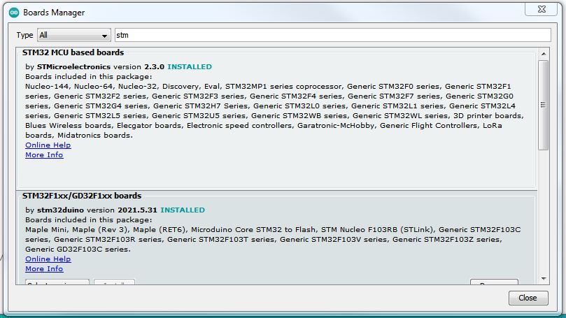
Setting up Arduino IDE for uploading a sketch.

I had to play a bit with the configuration of the Arduino to get it to work. The configuration in the picture shows my working configuration. The upload of the sketch where done with the same wiring as when the boot-loader where flashed.

The configuration that makes the USB work for my application.

Universal field-strength and power meter.

After some time i have started on the power-meter project again. I decided to more or less start form scratch. The main reason is because I introduced my project to the Lab group at LA1J ( LB1IF; Tommy, LA8DTA; Kjell Kristian, LA9XFA; Eivind and LA3NO; Jens).

As we are 5 participants on the project without any specified design all of us are building variations of the same project.The only thing all of us got in common is that we are all using the AD8307 and Arduino.We are probably ending up to build totaly different projects.


My plan for the project!

  1. To be able to fit in a Hammond 1590 box.
  2. Digital display from Nokia 5110 (84×48).
  3. Display dBm
  4. Display power in W, mW, nW and possible pW.
  5. Set up compensation for front connected attenuator probably by rotary encoder.
  6. USB logging possibility.
  7. Future linarisation / calibration feature.
  8. Learn more programming with Arduino.

My schematics is going to end up looking something like this.

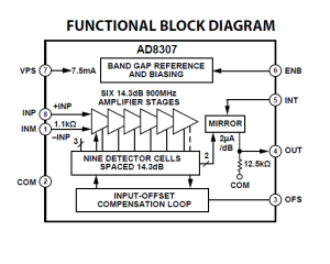
FSM AD8307

I have a prototype in place and it is playing along with the arduino, currently showing dBm.


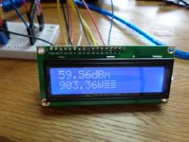
Got LCD

I have updated the code to facilitate LCD display. It is a 16×2 display.

The code is a bit messy but I’m getting there. The main issue right now is that I don’t know how to wipe the previously used fields. Hopefully I can get some support on the Arduino.cc web.

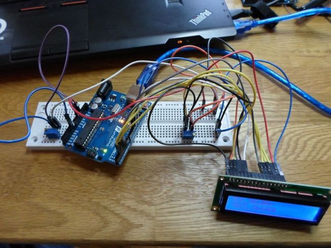
Today I managed to solve the issues with resolution on the DAQ and did some testing with a pot meter to simulate the AD 8307chip.

To be able to use the whole span of the DAQ I’ll use an OP amp to lift the 2,5 V 1000 W @  to 5 V @ 1000 W. The software will divide the calculated input voltage by 2 ant then I’m good to go. The resolution will be 5 V / 1024 instead of  5V/512.

Next task will be to find a suitable  OP amp. Ebay is my friend!

Bilde


Just now the project looks like a rats-nest of wiring, bread-board and circuit boards. Hopefully I can have something to show on Wednesday at the group meeting.

Bilde


The code!

I guess that the code might be of interest as well. It is basically just a bare bone that will display in the serial monitor. But it is working reasonably ok. I have decided to use a op-amp with 2x amplification to solve some of the resolution problems with the DAQ. The exiting thing is if i got any floating about in my spares/ junk box 🙂

I’ll whip up some proper schematics in a while.

My coding is not at a very high level but I’m getting there. The Arduino.cc web got a lot of information and the forum is helpful. http://arduino.cc/en/Reference/HomePage

The code is in progress.

/*
RF_pwr_meter
Reads an analog input on pin 0, converts it to voltage, dBm and W and prints the result to the serial monitor.
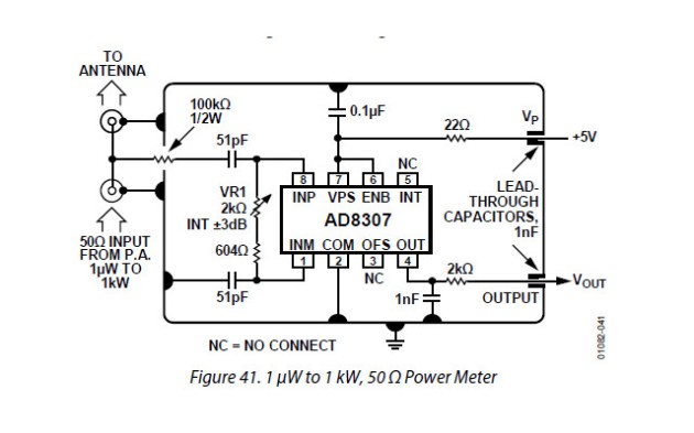
The hardware are based on the AD8307 log amp( power detector) see page 21 fig 41 in the datasheet.
*/
void setup() { // the setup routine runs once when you press reset:
Serial.begin(9600); // initialize serial communication at 9600 bits per second:
}
void loop() { // the loop routine runs over and over again forever:
//int P=0;
float sensorValue = analogRead(A0);// read the input on analog pin 0:
float voltage1 = sensorValue * (5.047 / 1023.0); // Convert the analog reading (which goes from 0 – 1023) to a voltage (0 – 5V):
float voltage = voltage1/2; // divide by two because of 2x opamp on input
double dBm=(40*voltage-40); // calculate dBm
double Pu= pow( 10.0, (dBm+30) / 10.0); //pwr in uW
double Pm= pow( 10.0, (dBm) / 10.0); //pwr in mW
double Pw= pow( 10.0, (dBm-30) / 10.0); //pwr in W
Serial.print(voltage); Serial.print(» V «);
Serial.print(dBm);Serial.print(«dBm «);
if (dBm <= 0) goto PrintPu; // jump to print uW
if (dBm >= 30) goto PrintPw; // jump to print W
Serial.print(Pm); Serial.println(«mW»); // print mW
PrintPu :
if (dBm <= 0) Serial.print(Pu); if (dBm <= 0) Serial.println(«uW»); // print uW
PrintPw :
if (dBm >= 30) Serial.print(Pw); if (dBm >= 30) Serial.println(«W»);// print W
delay(1000);
}

My first blog and Arduino.

I’m a Ham op LA9XNA and have just started with Arduino.

I got the boards a few months ago but have not got started until now.

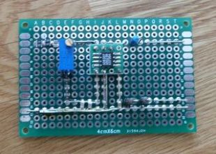
Last weekend i started building a RF power detector with an AD 8307 log amp. Bilde

The plan is to make an inline power monitor. Bilde

In the future it will probably be an full scale SWR monitor.

The plan for this project is as following.

  1. Make the hardware for the power detector. Done.
  2. Start to make the code in Arduino. Done.
  3. Test the code in an simulated environment by simulating the input voltage with an potmeter. Done.
  4. Modifie the code to optimize the DAQ resolution. Done.
  5. Make routines for 16 x 2 display.
  6. Transfer the code from Funduino UNO board to a Arduino mini board.
  7. Make a prototype.
  8. Testing.

In the future it might be evolve to a Pc or Android interface, But that depend on if i manage to get some better programming skills or if I can get help for the programming.

I got a lot of other projects thought up as well but I guess that not all of the are going to be realized.

The power detector are the one from the datasheet in the AD8307 manual on page 21. http://www.analog.com/static/imported-files/data_sheets/AD8307.pdf