T3FD the resistor (part 2)

The W4RNL PDF decribes a resistor of 800-900 ohm.

After doing some exercises in a excel spreadsheet I found that a serial parallel combination of 12 in series by 7 in parallel will give a resistor of 805,7 ohm.


In the beginning I considered using SMD resistors but found it a bit troublesome to get the resistors and would also have to design and get manufactured a PCB for the resistors.

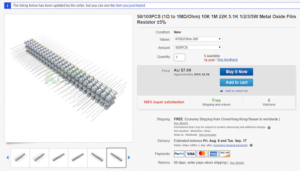
Instead I decided to go for regular axial resistors. I found a supplier on E-bay that sold 3W 470ohm 5% resistors in bags of 100 for a reasonable price.

resistor ebay


To mount the resistors I decided to make PCB. To simplify the manufacturing of the PCB I went for the quick and dirty method of doing the layout. I measured the length of the resistor body 17 mm and  rounded that up to 20mm. Two strips of PCB 45mm wide and 300 mm long where cut.

20190722_205654

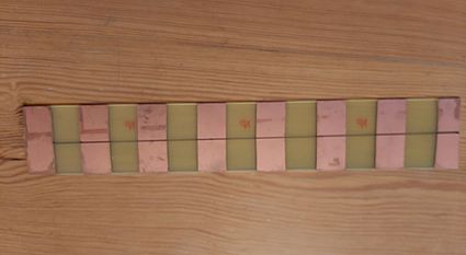
The I used 3M 33+ electricians tape and masked of the with of the tape every 20 mm. The PCB where etched in a FeCl solution, it where a bit time consuming because the etching solution where not at the optimum temperature.  In the end I had to make two boards to tit all resistors because of the length of enchant tank and size of the available PCB material.

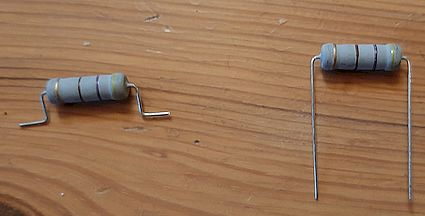
I bent 84 resistors in the shape of a top hat like showed in the picture.

resistor

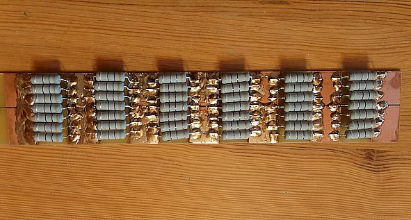
To get the resistors reasonable aligned I made a line along the center of the PCB lengthwise and soldered six resistors on top of the line. This would make it simple to just solder 3 on each side.

20190722_210954

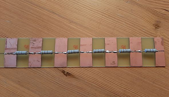
After about an hour of soldering and bending resistors I ended up with one of these and in about another hour I had two of these.

20190722_205700

T3FD antenna. Part 1.

For a long time I wanted a broadband dipole. Most of the broadband dipole antennas of the T2FD and T3FD variations are marketed for commercial users like the military, governmental agency and NGOs and is therefore in a price rang not favorable for a ham. Manufacturers of commercial antennas are companies like Bushcomm, Codan Communication and Barkers&Wiliamson. There are also other manufacturers but most of them are in the same price rang or have export restriction when it is manufactured in the US.

The US export restrictions are based on that some equipment can be considered as military equipment. But I think that most of the time it is the manufacturers that don’t want to use the sorceress and time to check if it is actually covered by the US legislation of materials that can be considered as military equipment.

To save money and don’t have the hassle of dealing with Norwegian  or any  other country customs legislation I decided to go ahead to build one.After searching the internet I found some building-plans at the HF link website. Here i found some information about a PDF from LB Cebik W4RNL (sk)                              Notes_on_Wide_Band_Multi_Wire_Folded_Dipoles_by_LB_Cebik_W4RNL.

The W4RNL PDF contains all the information I need to build  wide-band dipole antenna. There are variations of the wide-band dipole, but the most common variations are the T2FD and T3FD. After reading the PDF form start to end I decided to build the T3FD because this have a flatter SWR along the whole frequency range.

Description of the antenna.

The antenna is described in lengths of 89,14′ and 90′. Because I bought a 100 m length of 2 mm stainless steel wire I will make the antenna a bit longer and cut it down a bit to tune for lowest SWR.

The resistor is 800 ohm because this will give a flatter and lower SWR than when using a 450 ohm resistor.

Balun will be a 10:1 balun made with 43 material binocular core.

The spacers will be fiberglass fence-poles used on electric fences.


To build the antenna the following parts will be required.

  1. Terminating resistor 800 ohm.
  2.  Ferrite material for the balun.
  3. Antenna wire stainless.
  4. Fiber glass spreaders.
  5. Isolators.
  6. Housing for resistor and balun.
  7. Fasteners and crimps.